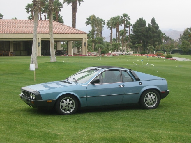
Getting There…

I reached a big milestone last weekend – the car moved under its own power!  I drove it out into the driveway and let the engine run for a while.  My test was aborted due to a fuel return line leak (fixed now), but it felt good to actually have the car out of the garage and in the driveway with the engine running.  It sounds great, love the V6 idle.

I had a problem with my clutch since I had a 7/8″ master clutch cylinder installed in my Tilton pedal assembly.  Clutch pedal force with this combination was brutal, so I ordered a 5/8″ master cylinder and installed it over the weekend.  It now feels like a normal car.  There is still some air in the brake lines, but the brakes work, as does the parking brake.

There is a rats nest of wiring still to be connected, and an interior to be reinstalled, but I feel like I’m well over the hump and that the end is in sight!

img_7820

Keeping Cool

The cooling system design was a LOT harder than I anticipated.  How hard could it be, right?  Because I was determined to stay with the stock fuel tank location, I found that it was directly in the way of the coolant route from engine to underbody coolant pipes.  One thing I learned from past swaps is that you also want to leave room for your hand to get in to spaces between various components in the engine compartment.  Otherwise, you’ll be swearing at yourself when you’re trying to service something installed long ago that’s now totally inaccessible.

My solution was to give the pipes a detour over the gas tank then back to the engine, to give access to the clutch cable area.  I created a pair of SS extension pipes, which also served as mounting points for the dash gauges (water temp gauge and overheat light sensors) as well as bleed valves.

img_7751

Below are stock reproduction SS pipes that I ordered from a race shop back East, modified to fit my application, with the pipes above before I added the fittings.

img_7745

These two sets connect together with straight hose along the firewall.  For the connections to the engine, I bend up brake line to match the centerline of the hose path, and head to my local Napa parts store and comb through their stock area looking for radiator hose that matches my application.  It gets really difficult when both hose ends are different diameter, but I lucked out and found a hose that worked pretty well.

I added a fitting at the front of the coolant pipe that connects to the top radiator for the heater, saves a second run of heater pipe.  I then repurposed that heater connection on the engine for the coolant overflow tank.

Breathe Easy

The intake manifold was one of the easier parts of this project.  A 3″ aluminum 90 degree bend, a K&N filter, and a couple of hose fittings and a mounting bracket welded on, and done!  Picture is looking at the front side of the engine.

img_7728

Lube Job

The stock location of the Acura oil filter ended up too close to the arc of travel of the rear suspension arm for my comfort, so a remote filter setup was called for.  This also gave me a place to add oil warning light and oil pressure sensors for my dash gauges, as well as a future oil cooler should it be needed.  I couldn’t find an aftermarket kit that solved the clearance problem, so I bought a used filter housing assembly, hacked it up, and TIG welded female aluminum NPT fittings for remote hose connections.  It’s a bit tricky as the internal passages are convoluted – it’s a 3-D problem to work out.  You also need to control the welding heat so that you don’t distort the precision VTEC piston bore (AMHIK!).  I don’t like using sharp 90 degree fittings, but that’s all that will fit in the space between crank pulley, chassis frame and suspension.  I did drill them out to reduce the internal restriction at the intersection of the bores.

Another challenge with this swap is that the oil filler cap ends up in an inaccessible position next to the firewall.  Rather than cut a hole through the firewall and add oil from inside the passenger compartment (yuk!), I cut a 2″ hole in the rear cam cover and welded on a filler cap and tube that I salvaged from a dry sump oil reservoir.  The only available hole location cuts into the PCV blowby chamber, so a hole saw works best here for allowing retention of the chamber wall geometry.080

Finally, I added an additional bend to the dipstick tube to make it easier to access.  083

I took the opportunity while the engine was out to replace the timing belt, bearings, tensioner and water pump, since the maintenance history of the car was unknown.  This is an easy job when you have full access to everything.  It paid off for me as well, since I discovered that the rear cam timing was retarded by one tooth!  Sloppy repair work by someone before me…

All Fired Up!

The wiring is progressing.  The front fuse/relay panel is mostly connected, see below.  I labeled all the wiring for future reference.  The Littelfuse fuse/relay box works great, highly recommended!  With good wiring, fuses and connections, the electricals are working better than ever.  The electric windows never went up and down so fast, just like a real car now!

At the back, I’ve finally finished deciphering, disassembling, and grafting the engine wiring harnesses into my rear fuse/relay panel.  It looks simple but there’s a lot going on behind the panel.  For now I’m retaining the original Acura ECM, which is located directly behind the panel.  AEM makes a programmable ECM which might be a future upgrade.  On the right is the connection diagram I made for the front and rear panels.

After double all checking the connections, I turned the ignition key and it started!  The engine was hunting pretty badly at idle.  I did some web research, and apparently the IAC is notorious for sticking on this engine.  A couple of whacks with a screwdriver handle fixed it.  There is still a lot to do before the car is back on the road, but today felt like a milestone.


Wires Wires Wires

There’s a scary rats nest of wires behind the dashboard as well as throughout the car.  If you follow the wiring path, you’ll find many wires take several detours on the way to their destination.  That’s fun if you’re talking about back roads and an afternoon drive, but not what you want for an efficient electrical system.

040

Given also that I need more/different wiring to handle all my modifications, and that the original wiring (not to mention fuses) were barely adequate for a stock vehicle, I elected to rewire the car from scratch.  I started by running 2/0 welding cable from the battery to the starter, and created two new wiring panels, one at the front and one at the rear.  This reduces the amount of front-to-rear wiring, and cuts down the rats nest of wiring from trying to run all circuits in the car from a single panel.  I re-purposed the original starter cable to feed each panel.  Each panel houses a Littelfuse universal style waterproof relay/fuse box that uses Metri Pack 280 style connectors and can be configured for a mix of blade type fuses and compatible relays.

HWB60 001
HWB60 001

I’m using dual circuit Blue Sea junction boxes to feed circuits that are 1) always hot and 2) hot on run.  A separate relay (not shown) energizes the hot on run circuit to remove the current load from the ignition switch.  The front panel (below) will run radiator fans, wipers, lighting, horn, windows, heater blower and accessories.  My primary headlights are HID and run off their own controllers.

042

The rear junction box circuits are 1) always hot and 2) hot on run plus start.  The rear panel runs the fuel pump, coils, injectors and ECM.  I’m using the stock Acura ECM for now, but AEM makes a nice aftermarket unit that I plan as a future upgrade.

036

Stop it!

Brakes – one of the major weak points of the Scorpion.  Power brakes on the front wheels only (where there is no weight), what were they thinking !?!  Plus 9″ diameter non-vented rotors are totally inadequate for any significant horsepower boost.  I was previously running 10″ vented rotors from a 2nd series Toyota MR2 Turbo at all 4 corners with reasonably good results, even at demanding tracks like Laguna Seca.  For better pedal feel and adjustability, I’ve swapped out the original brake & clutch pedal assemblies with a Tilton pedal assembly, featuring dual master cylinders and a balance bar which allows front/rear brake proportioning.

To further improve heat capacity and control, I started a search for uprated rotors and calipers.  As an educated guess, I bought a Stoptech front rotor for  a current generation FIAT 500 Abarth, and found that it fits the Scorpion hub perfectly!  I will be using these (11.1″ directionally vented) at all 4 corners, along with Wilwood 4-pot calipers (rear-heavy cars like the Scorpion can take advantage of large brakes at the rear).  Wilwood makes a small mechanically operated parking brake caliper, which solves one of the problems when fitting racing brakes on a car that sees street duty.  I had to add a spacer to the parking brake since it was designed for a slightly thinner rotor.  The rear caliper bracket is shown below.


012

September 2016 update:

Shopping for 16″ & 17″ wheels to fit the new brakes, and not finding anything I like so far.  Is is just me, or are new wheels all over-the-top complicated?  I want something that complements the Scorpion styling and isn’t trying to steal all the thunder.  Plus, a wheel that can be cleaned in minutes, not 10’s of minutes or more.  Just for fun, I mounted my 15″ Exip track wheels on the car, and was amazed to find that they fit!  The clearance to the wheel weights is almost nothing, but that’s solvable.  Here they are:

img_7824

Fuel Tank

I prefer the tank in its original location to preserve trunk space, but the V6 engine interferes with the tank.  You’ll notice that there’s a fair amount of empty space between the side of the tank and the inner wall of the side of the car, so my solution was to cut the lower outer corner off the tank and slide it over a couple of inches to that it sits over the frame rail.  Capacity is reduced by about a gallon or so, not a big deal for me.

IMG_6895

TIG welding is recommended to minimize the chance of leaks.  I also coated the inside of the tank with gas tank sealant, which will also help protect the tank from rusting.  Fuel tank mounting is shown below:

IMG_6897

Shifter

I’m totally sold on cable shifters, as is just about every auto manufacturer in the last 10-20 years.  Shifting is precise and positive, the shifter doesn’t move around with engine torque, and space consumed is minimal.  I cut down the stock Acura shifter mechanism to fit the center tunnel and mounting holes that I had added for my 16V Thema Turbo project, which used a first generation Toyota MR2 mechanism.  It was much simpler to change over to the Acura unit since the cables fit the mechanism, and the l0ng shifter cable was almost exactly the right length to attach to the transaxle.

IMG_6886

The short cable is now way too short, since the cables are coming from the front rather than from behind the transaxle.  I built a simple mechanism with a link to extend the length.  The assembly below relocates the shifter cable housing attachment points, with the cables oriented at a slight angle to clear the fuel tank.

IMG_6835

Here is the mechanism bolted to the transaxle with cables in position.

IMG_6950

Exhaust

A challenge with the Scorpion is designing an exhaust system to fit in the area between the engine bay and rear bumper given tubing bend radius limits, and it’s even more difficult with a true dual exhaust.  The Acura dual exhaust is not really a dual exhaust, as both manifolds feed into a single pipe, with the rear exhaust going through a 180 degree bend before it enters the single pipe.  My design is a true dual exhaust, with 2 catalytic converters and 2 mufflers.  The benefit of my engine choice started to become evident here, as I was able to purchase stainless steel headers of decent quality with a connector pipe for the grand sum of $300!

IMG_5950

The above shows a mock-up of the final system (all stainless) before final welding.  I did fire it up and it was loud, but not excessively so.  Probably over the sound limit at Laguna Seca, though…

IMG_6118

Currently, here’s what it takes to make the engine run!  Next step is to remove the 95% of the wires that don’t have anything to do with engine operation.