
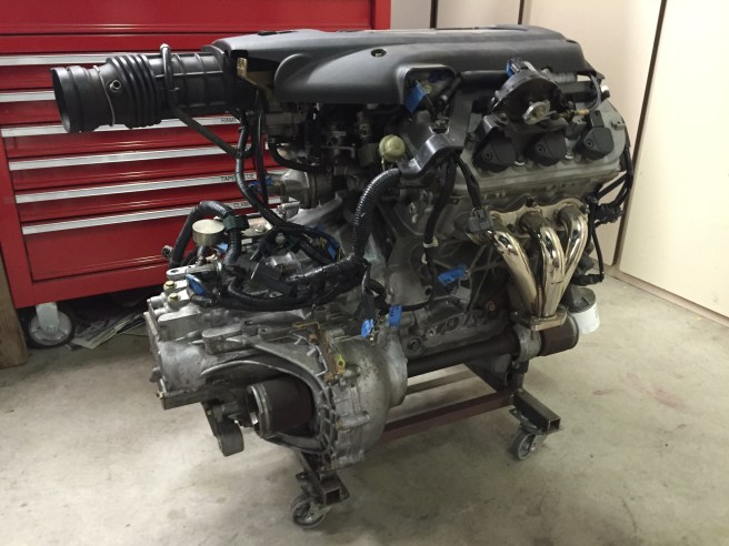
The first step is positioning the engine properly within the engine bay. I built a dolly that supports the engine at the desired height (6″ ground clearance) as an aid. Here’s the engine on the dolly:
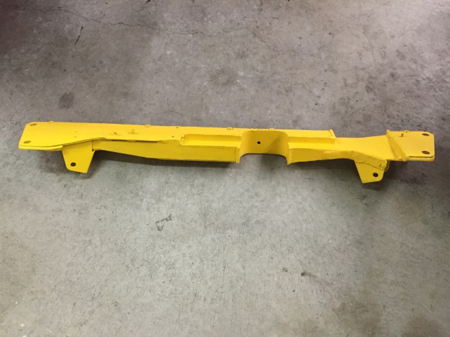
Then it’s a matter of centering the axle CV joint flanges left-to-right, and matching the engine CV joint centerline front-to-rear to the centerline of the rear wheels. I try to retain the original engine motor mounts where possible since they’re engineered for the particular engine. This engine had some heavy cast iron mounts that I ditched in favor of welded steel replacements, and of course the chassis-side mounts are all custom to fit the Scorpion. For this engine, significant crossmember reliefs were required, mostly for the front exhaust, but also various other engine components. The resulting crossmember was substantially reinforced to compensate for all the cutouts.
Fabrication of the motor mounts requires a lot of head scratching, as there are many possible options. I tried to minimize any permanent intrusion into the engine bay, and ended up with none at all. The process of fabricating motor mounts is a multi-step process, as measurements are difficult, and things shift as you apply the engine weight. The mount pieces are cut up, and tack welded together, then broken and tacked up again as needed until the positions are correct and welding can be completed.

The motor mounts, from left to right:
- Transaxle mount – I’m not sure how important this mount is, and the swap kits for dropping this engine into your Honda Civic don’t include this mount. I’ll probably try with and without.
- Rear motor mount – bolts to the Scorpion bulkhead behind the engine, which I’ve already reinforced to handle the load.
- Passenger side mount – I welded a bracket onto the right rear fender well to attach the top of this mount, and the bottom bolts to the frame.
- Front mount – this attaches to the crossmember. The bracket shown below the stock mount provides a platform at the correct height, and is removable to allow gas tank removal without removing the crossmember. This mount is vacuum controlled via a solenoid valve, which I assume leaves the mount soft at idle and stiffer under load.
The stock front and rear mounts include shock absorbers, but I’m going to hold off on these until I see whether or not they’re really required (there’s no top “dog bone” mount). Below are the engine compartment attachment points that I added. To create attachment points in the frame, I drilled holes and welded in nuts flush with the surface.


Here is the crossmember with rear motor mount and transaxle mount installed.
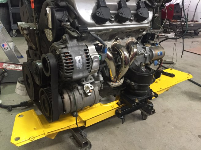

And views below with mounts installed and the engine in place – transaxle mount, rear mount, and passenger side mount.


